Tips for Plastic Injection Molders
Plastic Mold Building Tips
I’m sure you’ll agree with me when I say:
Building a perfect plastic mold is really complicated.
Or is it?
Well, it turns out that finish this job may not be as hard as you’d have thought. All you have to do is to check the following building tips and follow them.
In this article, I’m going to show you exactly how a good moldmaker to do.
If you want to know more, all you have to do is read on…
-
MACHINE

1 - After installing a mold, check the alignment of the machine nozzle to the mold sprue bushing with a thin piece of cardboard (shirt cardboard) placed between the nozzle and sprue bushing.
Bring the nozzle to position and take a shot right through the cardboard.
Pull back the nozzle, and you will see an impression in the cardboard that displays exactly how the nozzle is aligned with the sprue bushing hole.
Make necessary adjustments to bring the 2 together exactly.
2 - Ideally, the injection unit should be sized so that it contains two full cycles' worth of material.
In other words, 50% of the capacity of the injection cylinder should be emptied every time a cycle is completed.
This is referred to as the amount of “shot” a machine takes for each cycle because all of this material “shoots” into the mold during the injection phase.
In fact, you are using a half-barrel to make one shot while the other half is preparing for the next shot. This gives you the greatest degree of consistency.
The 50% rule is ideal, but a shot size should never be outside the range of a minimum of 20% or a maximum of 80%.
For example, if the total amount of material that is used for one complete cycle is 2 ounces, the ideal injection unit for that application would exist on a machine with a 4-ounce cylinder because 50% of 4 ounces equals 2 ounces, which is the initial requirement.
And, using the 20% to 80% minimum/maximum limits, the 2-ounce shot could be produced on as small a machine as one with a 2-1/2 ounce cylinder (80%) and on as large a machine as one with a 10-ounce cylinder (20%).
What determines this is the heat sensitivity of the specific material being molded.
Some materials are very heat sensitive and burn easily, while others are much less heat sensitive and are able to withstand longer exposures to elevated temperatures.
Heat sensitivity of a specific material is critical because it determines the amount of residence time that the material is allowed to stay within the heated injection cylinder before it begins to degrade.
Degraded material will not produce quality products.
The 50% rule-of-thumb noted earlier ensures that no material will degrade while being molded regardless of its allowed residence time.
The 20% rule-of-thumb applies to materials with low heat sensitivity, such as polyethylene.
And the 80% applies to materials that extremely heat sensitive such as PVC.
3 - Injection units are universally rated by the amount of polystyrene they can hold.
A conversion is required to determine how much of any other plastic they can hold, and this is done by comparing specific gravity values.
The specific gravity value of the other selected material (for example, polycarbonate) is divided by the specific gravity value of polystyrene to determine how much of the other material can be held in the cylinder.
For our example, the poly-carbonate s.g. of 1.20 is divided by the polystyrene s.g. of 1.04, giving a value of 1.15.
That 1.15 value is multiplied by the machine’s rating in ounces. Let’s say our example machine is rated as an 8-ounce machine.
That means it’s capable of injecting a maximum of 8 ounces of polystyrene. If we multiply that 8-ounce rating by the value we found earlier of 1.15; we find that it may also inject up to 9.2 ounces of polycarbonate.
4 - The injection temperature control indicator settings do NOT display the actual temperature of the plastic melted material.
It should only be used as a reference point. The actual melt temperature can only be measured by a probe that checks the material as it leaves the nozzle of the molding machine and enters the mold.
There may be as much as 30 degrees or more difference between those 2 readings, but the one that determines process conditions is the one that is taken by the probe.
5 - In most cases, the injection barrel heats should be established such that the plastic is heated lower at the rear zone and increased to be hottest at the front zone, with the nozzle set to be approximately 10 degrees (F) higher than the front zone of the barrel.
6 – If the injection screw turns while it is injecting material during the molding process, it indicates that the check ring is worn or cracked and must be replaced to maintain pressure on the plastic material.
7 - The Clamp Unit of an injection molding machine is rated by the maximum amount of clamp force that the machine is capable of producing.
This force is required in order to keep the mold closed during the injection process.
You should only use enough clamps to overcome the injection pressure as the excessive clamp will damage the mold.
For example, if you need 10,000 psi of injection pressure (5 tons), you would need only about 12,000 psi (6 tons) of clamp pressure to keep the mold closed.
8 - Use a machinist’s level (not a carpenter’s level) on tie bars when installing the machine.
Check for levelness every 6 months. An out-of-level machine will disrupt the process and material flow and could indicate machine frame warpage or floor settling.
9 - When laying out a floor plan, leave a minimum of 3 feet clearance around the entire molding machine footprint (including hoses and overhangs) to allow for maintenance, product flow, auxiliary equipment such as mold temperature control units and walkway for movement between machines and walls.
10 - Machine heat exchangers should be descaled at least once a month to make sure no scale deposits interfere with the unit's effectiveness.
A 1/64” of buildup in the heat exchanger lines will result in a 40% loss of the cooling ability of the hydraulic oil used to operate the molding machine.
11 - For accuracy, measure actual melt temp with a probe as it leaves the nozzle instead of relying on temperature control settings.
12 - Make sure your screw rotation speed is set properly. If not, you may find burn marks, flash, trapped air pockets, and a variety of other unexplained defects.
13 - Backpressure should never be less than 50 psi and never more than 300 psi.
The lower settings should be used for heat-sensitive materials like PVC, while the higher settings can be used for less sensitive materials like polypropylene.
If in doubt, set the backpressure for 50 psi and only increase if necessary.
14 – When opening the mold, make sure the machine opens SLOWLY for the first 1/8” or so to allow time for the vacuum created by plastic entering the cavities in the mold to be eliminated.
This vacuum will keep the mold halves from separating and may pull the mold right off the platens if you open too quickly.
15 – When closing the mold, do so in 2 steps, the first being fast, and the second switching to very slow in the last ¼” or so.
Quickly slamming the mold halves together will shock the steel and cause cracking of the mold.
16 – The heating cylinder is wrapped with a series of circular electric heater bands to provide the required melt temperature within the barrel.
These will eventually burn out, but if one does burn out, the others stay active to ensure the heat is still being applied.
Of course, the others must work harder to provide the same level of heat, so it is cost-effective to replace the burned-out bands as soon as possible.
A quick way of determining if a band is burned out is to use a plastic sprue created by the mold running in the machine at the time, or even a plastic part that was defective.
Rub the plastic against the heater band when it is supposed to be activated. If the plastic melts, the band is working. If the plastic does not melt, the band is bad and needs replacement.
When replacing a heater band, you must make sure you replace it with an exact duplicate. Check for dimensional size as well as voltage and wattage.
17 – When transporting it to be mounted in the machine, make sure that the mold has a connecting strap installed.
This strap should connect the two halves of the mold and keep them from coming apart during transportation.
Normally this is a metal strap mounted across the "A" and "B" plate parting line. It is not safe or proper practice to install the mold as two separated halves.
18 – When shutting down a machine, the injection barrel should be purged clean by running scrap polyethylene through it (acrylic can be used first if the color was being molded).
As the polyethylene is purged through the barrel, which can reduce heat.
After the material comes out clean, the injection screw should be left in the forward position, which basically empties the barrel. Only then can the heat be turned off.
Upon restarting the machine, let the barrel come up to whatever heat is required for the next run. The polyethylene will not degrade under higher heat.
19 - For the greatest degree of efficiency and the highest level of productivity, the flow of materials through a molding facility should be as close to straight-line as possible.
This is easily accomplished with a side-by-side machine layout but more difficult with any other format.
The raw materials should enter one end of the building and travel through required processes to exit as a finished product at the other end of the building. This includes packaging and preparing for shipment.
-
MOLD
plastic mold
1 - An injection mold should have a minimum of 6 parting line vents, more for larger molds.
There should be a vent at each inch interval around the perimeter of the molding cavity, and each vent should extend to the outer edge of the mold into the atmosphere.
These should be cleaned out at least once every 24 hours and more if needed.
There cannot be too many vents or too much venting. As long as the vents are of the proper thickness and length, they can be any width, and they can be any number.
A good rule of thumb is to allow at least 30% of the parting line perimeter for venting. The following drawing demonstrates this.
2 - If you believe a mold needs a vent somewhere that is not vented, you can create a temporary vent by placing two pieces of ½” wide masking tape on the shutoff land in the area in question, leaving a ½” gap between them.
That will act as a vent and allow you to mold 1 or 2 cycles to see what difference it makes in the molded part.
3 - Never use a single mold temperature control unit to maintain a water temperature between 2 mold halves.
Each mold half should have its own temperature control unit for complete effectiveness.
If only one unit is used for both halves, the water leaving the first half may not be at the right temperature for the second half.
Each half should be maintained separately to accommodate the specific needs of each half.
And both halves should never be at the same temperature, or you will not be able to ensure that the molded part stays on the half with an ejection system in place.
4 - Waterlines should be hooked to the mold after it is mounted in the press so that water enters the mold near the bottom and exits the mold near the top.
That ensures that any air in the mold lines will be purged out immediately and never cause hot spots in the mold during the production run.
5 - it should check mold temperatures periodically by using a flat probed pyrometer.
Each mold half should be checked separately, and the probe should be touched to 5 or 6 points on each mold half.
There should not be more than a 10 degree (F) difference between any 2 of those points or between the two mold halves themselves.
If greater differences occur, it indicates improper cooling conditions, and this should be rectified by cleaning lines, adding cooling channels, inserting baffles to the cooling lines, etc.
6 - A molded part will always try to stay on the hottest half of a mold. In most cases, we want that to be the Clamp Unit side of the mold because that is where the ejection unit is to push the final part out of the mold.
Warpage and sticking might be controlled by keeping this thought in mind.
7 - The ejection half of the mold should be 5 to 10 degrees (F) hotter than the injection half to ensure the molded part will stay on the ejection half.
Be careful, though, because too much heat difference will cause a “lockup” of the 2 mold halves or galling of some metal components.
8 - A hot mold will produce a part with a finish that has more gloss than a part molded on a cold mold. A hot mold will also produce a darker part than a cold mold.
9 - Use of commercial insulation sheets placed between the mold and the platens of the machine will result in less energy used for maintaining mold temperatures and create greater consistency of temperature throughout the mold.
These are available in ¼” or ½” thick sheets and can be permanently mounted directly on the clamping faces of the injection mold halves.
10 - To check for proper water flow from and to a mold temperature control unit, hold your hand on the outgoing and returning hoses.
If the unit is properly maintaining a set temperature, you should feel NO difference between the two hoses.
If the unit is not cooling enough, you will find that the return line is much hotter than the outgoing line.
That is because there is still too much heat in the mold, and the unit is not cooling it fast enough or efficiently.
11 - Mold waterlines should be descaled at least once a month to make sure no scale deposits interfere with the lines' effectiveness. A 1/64” scale buildup in a ¼” waterline will result in a 40% loss of cooling ability in the mold.
12 - Place a 1/8” (approx.) shim (metal washer) under mold mounting clamp heels to ensure downward force on mold at clamp toe.
This means the toe clamp should have its heel adjusted to point the toe slightly (1/8" is fine) towards the platen, as shown in the following sketch.
This must be done because it is impossible to maintain exact parallelism of the clamp to the platen as is desired for maximum clamping force.
Expansion and contraction of the mold and machine result in clamps slipping loose when adjusted to be perfectly parallel.
If the clamps are adjusted so the toe is pointing away from the platen, the clamping force is also pointing away from the platen, and the mold may fall out due to insufficient clamp force.
Therefore, the toe should be adjusted to point in towards the platen to ensure that the clamping forces are directed towards the platen.
13 - Replacing straight waterline fittings on the mold with right-angled fittings will increase the turbulence of flow for water traveling through those lines.
That will ensure good overall temperature control and mimics the “Reynolds Number” approach to mold temperature control.
14 – When checking mold surface temperature, take at least 3 readings in different areas where the plastic will touch the mold.
There should be no more than 5 degrees (F) difference between the 3 readings.
15 - Keep in mind that it doesn't really matter what the settings are on the mold temperature control unit.
What matters is only the temperature found on the mold itself and then only in the areas that will be touched by plastic.
If someone asks you, "What is the mold temperature?"
DO NOT give them the readings that are set on the controller.
Rather, give them the readings found by the pyrometer on the mold itself.
16 - Steel objects should never be used for removing stuck plastic from a mold or from a sprue bushing hole.
The steel will scratch the mold and sprue bushing, which will require expensive repairs.
Instead, use a wooden dowel, plastic putty knife, or brass tools.
17 - For removing a broken-off or sticking sprue from a sprue bushing, heat up a brass wood screw, push it into the stuck plastic and allow the plastic to harden.
Then clamp the screw head in a pair of brass pliers and tug the stuck sprue out of the sprue bushing.
The screw may easily be unscrewed from the plastic for future use.
18 - A copper or brass hacksaw-type blade can be heated and used for extracting stuck plastic from deep wall sections of a mold.
DO NOT USE STEEL blades as they will scratch the mold.
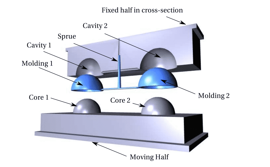
19 - Ideally, the injection gate should be placed so that the molten plastic enters the cavity image at the thickest portion of the part to be molded.
Then the material will be forced to fill the cavity and will get squeezed as it flows into the thinner section.
That causes resistance to build-up, which in turn creates a pressure buildup that helps finish the filling action.
You can only develop injection pressure by having the melt meet up with a resistance of some type.
While that does happen slightly while the material is moving through the heated barrel and into the mold, the high packing pressure buildup occurs only when the material fills the cavity.
20 - Molds are expensive, ranging from a few thousand dollars for small and simple molds to hundreds of thousands (even millions) of dollars for large, sophisticated molds.
https://www.plasticmoulds.net/tips-for-plastic-injection-molders


Comments
Post a Comment