Structure of Injection Mold
A mold is made from various
parts, including plates, pins, bushings, pillars, ejectors, and many other pieces of equipment that serve a number of purposes.
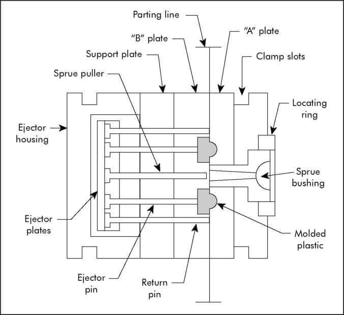
In Figure 1, the locations of the basic items that comprise the mold are shown and illustrate the mold in its closed position, which separates between the A plate and the B plate when the mold is opened.
Parting lines may be described as a line representing the boundary where a mold half parts or separates from another half.
Figure 1
It is known that the two halves of the separated mold are referred to according to whether they contain an A plate or a B plate. The half of the mold which contains the plate core will therefore be designated as the core half, whereas the half of the mold that contains the plate cavity will be designated as the cavity half.
Similarly, the core half is sometimes referred to as the moving half as well since it's usually home to the moving section of the mold, which contains the ejector system. The cavity half of the mold that normally contains no moving parts is called the static half.
The Injection system
Injection molds comprise several parts, including the sprue bushing, core and cavity plates, runners and gates, and a cavity.
The Sprue Bushing
The core half typically contains bushing, which was originally used in die casting. The term sprue is used to refer to the bushings used in die casting.
In an injection mold, the sprue bushing is the component that allows molten plastic to be injected into the mold's runner and proceed to travel along with it to reach the cavity. The runner system and the sprue bushing direct the material into the cavity through the gate. The runner system is the interface between the press and the injection mold.
This part is made from hardened tool steel and is highly polished for optimum effectiveness to minimize stickiness. It is a replaceable part of the mold. A sprue bushing is critical for typical molding applications where conditions are dictated by parameters such as viscosity of the molding material, the volume of material flowing through the runner system, and the thickness of the mold plate of half of the cavity-half of the mold.
Furthermore, there is also a factor in terms of the diameter of the orifice in the nozzle.
The core and cavity Plates
The mold components that form the molded part are the core and cavity plates(also A and B plate).
To take advantage of the ejector system (usually located in the core half of the mold), we mold the plastic product in the core plate whenever possible.
However, some situations in which the plastic product design requires some of the plastic parts to be placed in the cavity plate for surface-looking consideration.
Figure 2 shows the A and B plates from a standard two-plate mold used to make triangular plastic safety signs.
The mold is a two-cavity mold, meaning two pieces are molded at the same time.
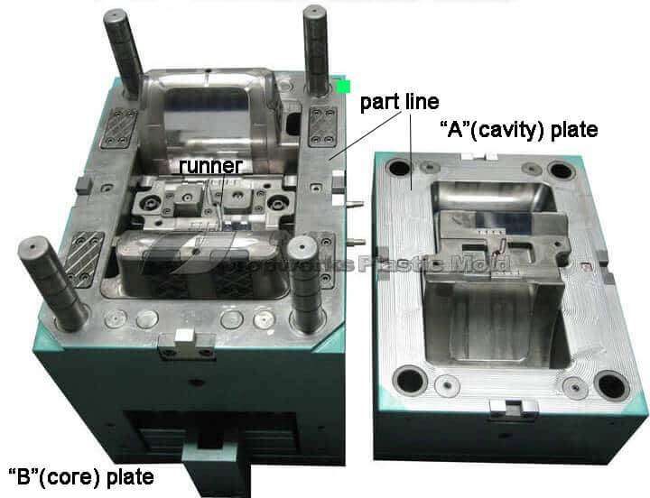
Figure 2
Runners and Gates
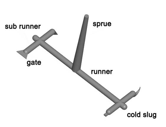
Injection molding is the process of heating molten plastic as it leaves the injection molding machine and enters the mold through the sprue bushing. Once it has entered the mold, the melt must be directed to the cavity image by the runner system and gates.
Runners are pathways that are carved into the surface of the mold base. These are usually created using a ball-end mill, but you can also use an electrical discharge machine to create the runner system.
As the gate is located at the end of the runner and is defined as one of the openings on a mold, it is considered a door.
Designed and constructed to allow molten plastic to fill the cavity within a relatively short period of time and to fill the cavity rapidly, but under a controlled condition, this cavity filling device retains its function and remains effective in this regard.
[caption id="attachment_5093" align="aligncenter" width="1135"]
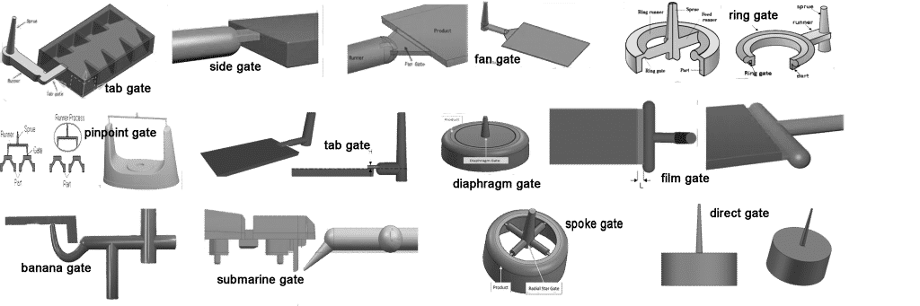
plastic mold gates[/caption]
It is essential to keep the gate as thin as possible during the injection molding process to ensure proper flow and play a huge role in determining the overall cycle time of the process.
It is technically feasible to fill any cavity image regardless of its size or shape with only one gate. Unfortunately, it is almost always necessary to take advantage of the flow characteristics and profiles provided by multigate systems in practice.
Several factors determine the final shape and size of the molded product. For instance, the shape and size of the final molded product are determined by the cavity cut into both A and B plate andy the specific characteristics of the specific molded material.
Common machining methods used for machining this image into the plates are milling, grinding, turning and stoning/polishing, which are common machining tactics.
There is no question that EDM (also known as EDNC or electrical discharge numerical control) is today's most commonly used method in the manufacturing process.
There is a method that utilizes an electric current to remove metal from cavity plates in the system. This method can be controlled to the point where it does not require any further machining if it is not required to have a high-polish finish on the cavity.
The Ejector Half
The ejector half of the mold comprises things like the ejector housing, the support plate, the support pillars, the ejector shaft and support design, the sprue pullers, and the guides for the ejector system.
The Ejector Housing
An ejector housing is a U-shaped box of metal that is formed in one piece. This is achieved so that maximum strength with little deflection or warping is obtained during the molding process.
To cut corners and make as much money as possible, some mold makers manufacture the housing out of bolted plates. This is an unsafe practice since, under injection and clamping pressure, the side rails will distort and crack, and the housing may fail.
Additionally, the distortion also causes the pins and holes in the ejector to wear out prematurely and excessively for a long period of time. The question is whether the fabrication process of this device was actually able to save any money, certainly not when the potential for danger and damage was taken into consideration.
An ejection housing is often used to contain the ejector component. The ejector component contains, for example, pins, bushings, guide pins, springs, and guide pins, as well as other parts which support its operation.
A guide on the ejector system components ensures that ejector wear is minimized, much to the advantage of the customer. Although this practice does add a slight amount to the overall cost of the mold, it provides a great benefit to the company in the long run.
Support Plate
In the ejector housing, a significant amount of unsupported section is located directly under the core plate of the mold, where it is shaped in the U shape.
The open area beneath the core plate causes the plate to bow or bend, which leads to distortion. The amount of distortion is on the order of 0.010 in. (0.26 mm). This is enough to cause a lot of flash on the parting line and quickly result in a weakened B plate.
The B plate is mounted directly behind a supporting plate to prevent major and minor distortions. This technique, consisting of two plates, the B plate and the support plate, provides much greater resistance to distortion than simply thicknessing the B plate.
Support Pillars
A support pillar is used to assist with the reduction (or elimination) of the B plate distortion placed between the ejector housing and the support plate of the mold. In addition to the support plate, support pillars are used to help reduce the distortion.
Ejector Pins, Sprue Pullers
They are made of steel, and they are round, with a flat face and a round head.
Once the injection molding process has been completed, a set of pins is used to remove the completed molded product from the mold.
Also, ejector pins are used for the surface-style runner system to be removed.
Only when a pin contacts the surface of a molded part or runner is it called an "ejector pin."
An ejection pin will leave an impression on the molded part where it has been inserted into the mold.
It is very common for the impression of the plastic to be either depressed in the material or a raised pad of excess material.
return pins
With the help of return pins, the ejector system of the mold can be pushed into its proper location before the next moulding cycle when the mold is closed.
The pins used in this process are not used as ejector pins because they do not come into contact with the surface of the molded part, but rather, they are interacting with the stainless steel surface of the A-plate during mould closing.
For the return pins to contact the ejector system, the return pins are forced back, and the ejector system is brought back to its proper location.
Sprue Pullers
This is a specific type of ejector pin that is more elaborate than an ejector pin, and it is designed to help release the sprue bushings from the mold when it has been opened for the first time after the injection process is finished.
The sprue puller pins are usually equipped with some under-cut on their end.
An undercut can be obtained in various ways, some of which are: a groove machined into the diameter of the pin, a Z-shaped notch molded into the diameter, or even a ring groove machined into the hole that receives the pin.
The undercut is placed in all cases, so material from the sprue will get trapped in the groove.
When the melt material inside the undercut begins to harden during the mold opening, the sprue tends to be pulled away from the sprue bushing.
The sprue puller activates the ejector system after the mold has fully opened and acted like an ejector pin, cutting off the undercut in the sprue on the B half of the mold.
Ejector System Guide Pins and Bushings
Gravity tends to pull the ejector system downward when the mold is typically horizontal, and this has a lot to do with how the ejector was designed.
During the process of doing this, the diameters of all the pins and the holes in which they ride will be stressed, which will cause the mold to develop an elliptical hole in it, which the flash inside of the mold will fill.
The use of guided ejector systems is one method to minimize the negative effects of gravity.
There are various methods by which the ejector system may be mounted to a vertical plane with the assistance of guide pins and bushings that are designed to maintain the ejector system in a horizontal plane at all times.
https://www.plasticmoulds.net/structure-of-injection-mold.html?feed_id=112&_unique_id=62a143ffee59f
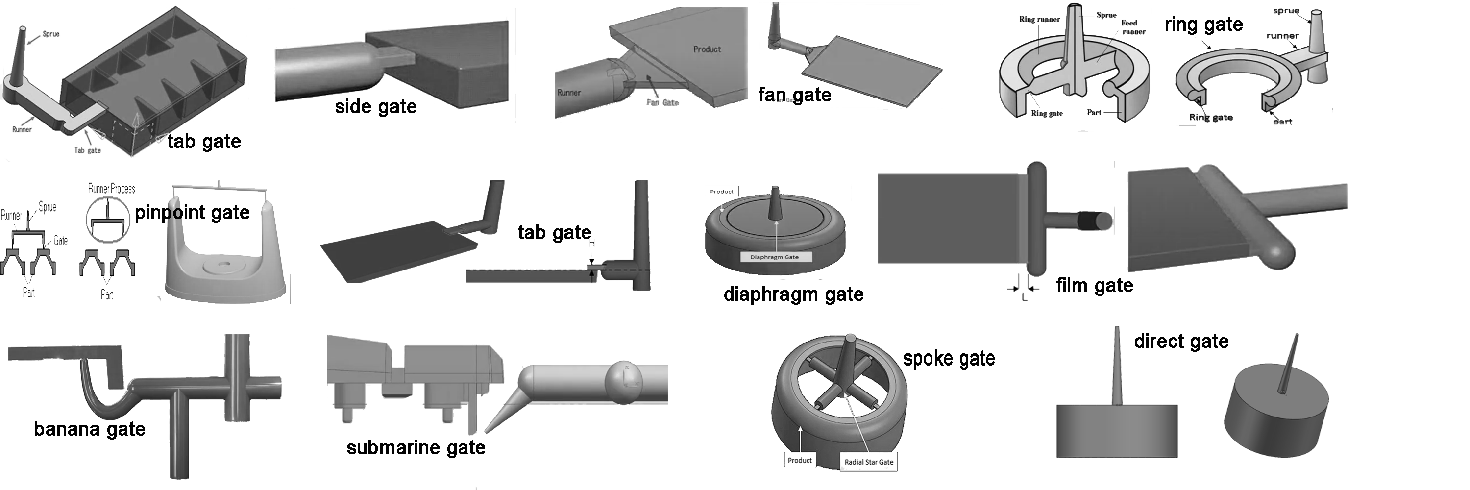 plastic mold gates[/caption]
It is essential to keep the gate as thin as possible during the injection molding process to ensure proper flow and play a huge role in determining the overall cycle time of the process.
It is technically feasible to fill any cavity image regardless of its size or shape with only one gate. Unfortunately, it is almost always necessary to take advantage of the flow characteristics and profiles provided by multigate systems in practice.
Several factors determine the final shape and size of the molded product. For instance, the shape and size of the final molded product are determined by the cavity cut into both A and B plate andy the specific characteristics of the specific molded material.
Common machining methods used for machining this image into the plates are milling, grinding, turning and stoning/polishing, which are common machining tactics.
There is no question that EDM (also known as EDNC or electrical discharge numerical control) is today's most commonly used method in the manufacturing process.
There is a method that utilizes an electric current to remove metal from cavity plates in the system. This method can be controlled to the point where it does not require any further machining if it is not required to have a high-polish finish on the cavity.
plastic mold gates[/caption]
It is essential to keep the gate as thin as possible during the injection molding process to ensure proper flow and play a huge role in determining the overall cycle time of the process.
It is technically feasible to fill any cavity image regardless of its size or shape with only one gate. Unfortunately, it is almost always necessary to take advantage of the flow characteristics and profiles provided by multigate systems in practice.
Several factors determine the final shape and size of the molded product. For instance, the shape and size of the final molded product are determined by the cavity cut into both A and B plate andy the specific characteristics of the specific molded material.
Common machining methods used for machining this image into the plates are milling, grinding, turning and stoning/polishing, which are common machining tactics.
There is no question that EDM (also known as EDNC or electrical discharge numerical control) is today's most commonly used method in the manufacturing process.
There is a method that utilizes an electric current to remove metal from cavity plates in the system. This method can be controlled to the point where it does not require any further machining if it is not required to have a high-polish finish on the cavity.


Comments
Post a Comment