Injection Molding Process
Injection Molding Process
Today, injection molding is one of the most widely used methods for fabricating plastic products. It allows a plastic part to be made entirely from a single cycle. Elastomers, duroplast, and elastomers can all be used with it.
We will discuss thermoplastic injection molding in the sections that follow.
A Concept of Injection Molding
Injection molding processing began in the nineteenth century when its earliest parts were rather simple, and the molding process had no automation. The main substances used were duroplast and elastomer, with the latter being molded, shredded or soaked.
Injection molding of plastic parts has become more efficient due to the development of injection molding machines.
The emergence of electronic control systems and later the microprocessor made it possible to manufacture mass-produced plastic items at even higher levels of automation.
A process for injection molding
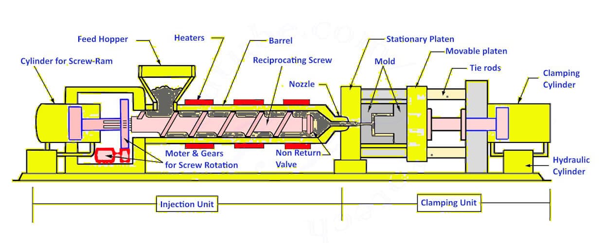
The pellets of raw plastic molding material are small and uniformly sized. Injection molding machines use gravity to feed the plastic into the injection cylinder. The heat tape and the friction of the screw in the cylinder heat the plastic as it enters into the cylinder.
Melted plastic pellets are heated, poured under high pressure into a mold that has been cut into the negative geometry of the part. The plastic fills out the form as it melts, forming the part.
The plastic solidifies as soon as it cools after injection, shrinking the part as it freezes. This shrinkage is compensated by keeping the part under pressure while it solidifies. Once solidified, the part is cooled and then de-molded.
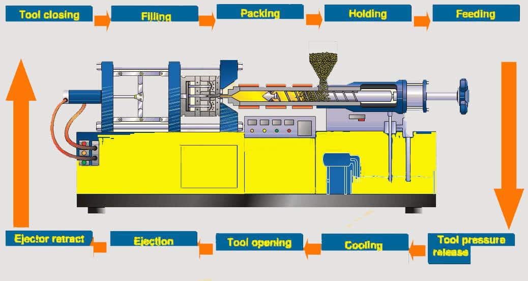
The process cycle is the way time and/or pressure can be controlled and measured. The cycle can be separated into the filling, injection, packing pressure, holding pressure, cooling, and de-molding
 Melting
The heated barrel and rotating screw is fed with material from the hopper.
By heat, friction, and shear force, the material melted by the rotation of the screw is forced through a check valve to the front.
Injection
The screw is forced forward from the back end by a hydraulic ram after having been moved forward by the shot of material at the front.
Cooling
The tool remains closed until the plastic has completely cooled and hardened in the mould tool cavity. This is usually the longest portion of the injection moulding process.
Ejection
The next moulding is performed by back-moving the screw. The tool opens and the plastic part is ejected. Next, the tool closes, and the injection molding process is repeated at 1.
The cooling process occurs simultaneously with packing, holding pressure, and filling processes.
Filling
The molding material is introduced into the injection machine cylinder into which heating tapes are inserted. The screw moves the plastic pellets into the cylinder in a circular motion, melting into plastic and becoming plasticized.
In the screw antechamber is melted plastic material, which is an amount measured equal to the amount of plastic needed for one injection molding cycle. The filling process begins after the plastic has reached the appropriate temperature to achieve shrinkage balance, and pressurization is applied to the process.
The following parameters are very important, especially the cylinder temperature, screw rotation numbers, holding pressure, packing pressure, back pressure, filling time, and the screw return cycle (decompression).
- -The cylinder temperature is dependent upon material choice. For instance, PE and PP are heated to around 180 degrees while PA 66 is heated to around 270 degrees, and PMMA is heated to around 270 degrees. Each plastic type has a specified temperature for its application. The number of screw revolutions determines rotation per minute. The filling time can be decreased, but if the speed is too high, the friction (shear of the material) may be too great, and this can cause the material to be damaged.
- -Backpressure: it is the hydraulic pressure used to run the filling process. A correct back pressure setting guarantees a better mix of the materials while guaranteeing uniform material delivery.
- -Filling time is the total amount of time it takes to fill up and tighten the threads followed by decompression, if that makes sense. Generally, it is recommended that the filling time be shorter than the cooling time.
- -A screw return system is used to return the screw to its original working position after filling. This increases the pressure in the screw-antechamber and the hot-runner, thereby reducing the possibility of leakage once the melted plastic has been discharged into the mould.
- -Packing pressure is the pressure required to fill the part and maintain an optimal temperature totally.
- -Holding pressure is applied to the material by lowering the screw speed, which then holds the pressure in place until the gate freezes. Holding pressure is maintained until the gate freezes.
Injection
The injection process involves the plasticization of the mold cavity by injecting melted plastic into the mold under high pressure by driving a forward trajectory of the screw.
Important Parameters: injecting speed, injecting pressure, injecting time.
The speed setting of the injection machine is determined by the plastic material and the mould design. The speed setting can be used to control the surface finishing, the filling, the orientation and the shrinkage of the plastic product.
The resin requirements for injection moulds are defined by viscosity, reinforcement, and other material additions such as colorants. Care must be taken when using high injection pressures when the mould contains parts with small cross-sections since high shear speed can overcure the plastic.
The injected screw speed is the only thing that is controlled with the injected injection speed since the material speed inside the mould is much higher than the screw speed (the smaller the cross-section, the higher the speed).
A machine's injection pressure is a function of its injection speed, as the electronic controls automatically determine the necessary hydraulic pressure based on the injection speed. On older machines, the hydraulic pressure could be individually controlled.
-Injection time is the time needed to inject the melted plastic. It can be used as a general guideline, where the after-pressure is to be manually adjusted (unfavorable because it is not constant).
-
Packing Pressure
After the injection process, the packing pressure is initiated to offset the shrinkage of the cooling component.
Important Parameters: packing pressure elevation, packing pressure time
-Packing pressure is the amount of pressure higher than the injection pressure required in order for the after-cycle to work (usually about 30 to 50% of the injection pressure, semicrystalline plastics shrink away from the injection pressure faster than amorphous plastics).
The duration of packing pressure is the time during which packing pressure is applied.
https://res.cloudinary.com/steven-cheng/video/upload/v1484569601/Injection_Molding_Animation_tjyyea.mp4
-
Holding pressure
Holding pressure is applied after the packing pressure phase occurs while the cooling part's gate freeze occurs.
Important Parameters: holding pressure elevation, holding pressure time
-The final pressure in the packing pressure phase is the holding pressure elevation. At this point, the screw stops, and the pressure of packing is maintained.
-Holding pressure time is the amount of time required to reach the gate freeze, which is the temperature at which plastic melts. If the screw is moved back before gate freeze, the loss of pressure results in the plastic melt flowing out of the mold and will result in an incorrect fill.
Freezing - The Cooling Process
Melted plastic begins cooling inside the mold after injection. The mold is typically built with cooling channels, through which coolant liquid can be circulated to remove heat from around the part. The cooling time required depends on the wall thickness; the thickness of the plastic part will determine the length of the cooling process.
The overall cycle time may be determined by both the thickness of the part and the cooling design.
A very simplified cooling calculation is
Tk = 2 x S²
Tk = cooling time S= biggest wall thickness
A more accurate cooling analysis can be performed with advanced calculations or simulations (MoldFlow, CadMould).
The parts must reach the required strength, shape consistency, and level of strength during the cooling phase before they can be de-molded. During the cooling phase, the filler unit (aggregate) preps the batch for the next machining operation.
A separate factor that influences cooling time is when the gate freezes. Good shape consistency of a part can only be guaranteed once the gate freeze point is reached since the shrinkage is lost in the process.
The gate may still need to be cooled further after it freezes.
Ejection
The ejection method must be tailored to the shape of the molded parts to avoid damaged products. In general, shrinkage on the mold cores is detrimental to mold release. Large ejection areas uniformly distributed over the molding are recommended to prevent deformation.
When no special ejection requirements have been established, the standard ejector pin can be utilized. For cylindrical components such as bosses, a sleeve ejector is used to ensure uniform ejection.
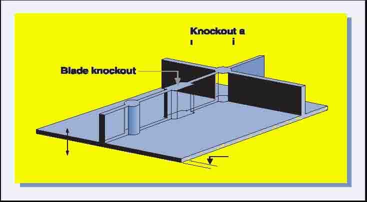
Blade ejectors are often problematic because they damage parts often, the plastic part can be damaged easily, and the injection mold requires a lot of maintenance. They are most commonly used with ribbed parts.
Under certain conditions, a centrally located ejector may be used together with an air valve insert. A high-gloss surface may impede mold release because it can cause a vacuum between the capillary wall and the mold.
The vacuum can be broken by introducing an air introducing mechanism.
When ejector pins and valves fail to operate effectively, a stripper plate or ring may be used. A chain or return pin is often used to operate the stripper plate.
Three-plate molds feature two parting lines when multiple cavities are formed or when multiple gates must be built. Parts are pulled away from the runners at the beginning of the opening stage of a three-plate mold.
The force required to eject a part could be calculated using the opening stroke of the mold to determine the minimum opening stroke required to remove the part.
https://www.plasticmoulds.net/injection-molding-process.html


Comments
Post a Comment