How to determine the Part Line of plastic mold
Items that determine the number of parting lines include:
- the geometry of the part to be molded,
- the number of cavities being produced,
- the type and style of runner system,
- the type of gating utilized,
- and the method of ejection of the molded product.
The primary parting line is always that which divides the A plate from the B plate. This is the plane that is exposed when the mold separates for opening and is shown in Figure 3. The parting line follows the contour of the molded part. The more complex the part contour, the more complex (and expensive) it is to create the parting line in the mold.

Figure 3
Ideally, the parting line should be a perfectly straight and level plane, but many part designs require the primary parting line to be stepped and/or contoured. An objective study of the part design will aid in determining the most efficient method and location for the primary parting line. All protruding (male) metal should be on the moving half of the mold, while all concave (female) metal should be on the stationary half of the mold. This is to ensure that, as the plastic cools and shrinks, it will shrink onto the ejection half of the mold, and away from the injection half of the mold.
Sometimes, due to special gate design caused by part design, it may be necessary to use a “reverse” parting line. In this case, the male components must be placed on the stationary half of the mold and the female on the moving half of the mold. When this occurs, it is necessary to place an ejection system on the stationary half of the mold because the cooling parts will shrink to that side.
Multiple parting lines occur when part design necessitates special mold design and construction, such as molds that utilize slide mechanisms to create undercuts on a molded part. One such situation would be the case shown in Figure 3. Here, a bobbin-shaped part is being molded. The round bobbin has a top face and a bottom face, each of which creates an undercut condition. These undercuts can be formed utilizing a slide mechanism that moves out of the way to allow the finished molded part to be ejected from the open mold. The moving action is caused by slotted holes in the slides following the stationary angled pins. When the mold closes, the slides move in again to create the area that will result in molded undercuts during the next molding cycle. Note that there are actually three parting lines created due to this design. The primary parting line is between the A and B plates, while a second parting line is created on the face of the slides, and the third parting line results from the top and bottom face areas of the slides.
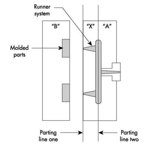
There are situations where our definition of a parting line must be stretched. One such case is with the design of a three-plate mold. The most common three-plate mold uses a floating plate between the A and B plate to house the runner system. The primary parting line is now between the B and X plate, and a second parting line is between the X and A plate. The secondary parting line does not actually form part of the part, but does form part of the runner system, which can be considered part of the part, by stretching our definition.
Shut-off Areas
There could be many places in a mold where components come together to form a seal while molding the finished product. These areas are called shut-off areas. The most common shut-off area is the primary parting line. This basically horizontal plane is commonly referred to as the “shut-off land surrounding the cavity,” . Unusual contours may result in a nonhorizontal shut-off condition.
The vertical shut-off condition causes an area of concern because of the potential for damage that may occur there. This damage could result if the mating shut- off angles are not perfectly matched, or if plastic flash, or other debris, should get trapped between the angles when the mold closes. In addition, there is a tendency for the mating shut-offs to gall or seize as they slide together to seal in the last fraction of an inch during mold closing. Vertical shut-off conditions should be avoided if possible, and utilized only if absolutely necessary.
One way that vertical shut-offs can be used is to construct openings in the side walls of products without using cams or slides. Note how splitting a localized shut-off between the A and B halves of the mold will result in an opening through the wall. The shut-off area should be made with inserts that allow easy adjustment and repair in the future, if the expected production volumes warrant the additional expense.
Regardless of how the shut-off is accomplished, there should be a planned interference fit of approximately .001 in. (0.03 mm) in constructing shut-off components. In addition, all shut-off areas should be designed such that interference can be adjusted (for example, through shims) after the mold has been running for a few hours or so, due to natural “settling,of the mold components.


Comments
Post a Comment