what is plastic mold?
What Is Plastic Mold?
What is plastic mold?
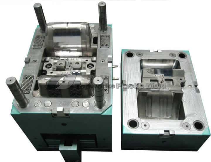
The tooling used for plastic injection molding is called plastic mold or plastic injection mold.
Most plastic products are molded by plastic molds.
Plastic molds are divided into two types: thermosetting and thermoplastic mold ,according to the molding plastic characteristics.
Based on the molding process, the plastic mold is divided into
- plastic injection mold,
- blow mold,
- casting mold,
- pressing mold,and so on.
The injection mold is made up of two main sections: the moving half and the fixed half.
The moving half is mounted on the moving platen of the injection molding equipment, and the stationary half is mounted on the stationary platen.
Over the injection molding, the moving and the stationary half are shut to develop an injection structure and a cavity structure.
Once the mold is open, the moving half and the stationary half are split up to clear away the plastic item from the plastic mold.
As a way to decrease the mold design and developing period, the majority of the plastic molds work with standard mold bases.
https://res.cloudinary.com/dl8a9jvpa/video/upload/v1572574321/plastic%20mold.mp4
The plastic mold is mainly composed of
- Injection system,
- Temperature control system,
- Part forming system
- Ejection system.

The injection system and the part forming system are in direct contact with the plastic and they change with the different plastics and products.
Those 2 systems are the most complex and most varied parts in the mold and require the highest finish and accuracy.
The part-forming process refers to the melted plastic heated by injection molding machine is injected into the mold cavity.
After cooling and solidification, it get the molded products.Which simplifies as :mold close - injection - pressure - cooling - mold open - ejection.
What is plastic mold?
The plastic injection mold is generally composed of the following parts:
- mold base: generally choose standard mold base from standard mold base manufacturing factory , such as LKM,DME,HUSCO...
- mold insert: it is used to form plastic products, plastic mold factory normally makes it by itself, most of the processing time is spent on the producing mold inserts.
- mold auxiliary parts: they include location ring, nozzle bushing, support pillar, ejector plate, guide bushing, guide pin, lifting ring and so on.
- the four major systems:
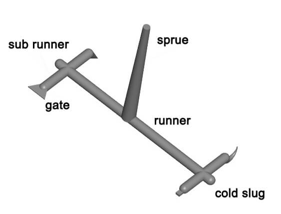
- 1) Injection system: The injection system refers to the flow path part before the melted plastic enters the cavity from the nozzle, including the main runner, the cold slug, the sub-runner and the gate.It is directly related to the molding part quality and production efficiency.
- 2) ejection system: ejector pins, blade pins and sleeves.
- 3) heating and cooling system: hot runner, pre heating device, cooling water;
- 4) venting system: venting slot, parting surface venting, ejector pin venting and insert venting;
- special mechanism: if the product has the undercut or side wall hole , the plastic mold needs to design the side core pulling mechanism (also called the slide), the inclined core pulling mechanism (also called the lifters), the oil cylinder (when the side core pulling distance is long).
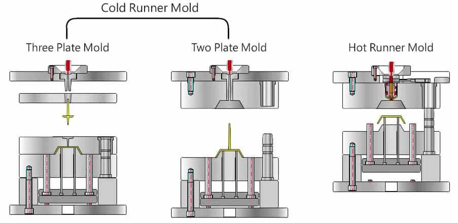
Classification of injection mold:
- 2 plates mold: another name of the sprue gate mold, also known as the single parting line type plastic injection mold, its characteristic is the simple mold structure, but the sprue is a part of the injection molded part, and it need to be manually removed later; 2 plates mold structure is widely used for various kinds of mold.
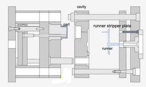
- 3 plates mold: also known as the pin point gate mold, also the double parting line type injection mold.Its gate characteristic is pin point, the gate cross section is small.The injection molded part appearance is good, and because it does not need the manual removal of the gate later, it is advantageous for the automation production.But 3 plates mold structure is more complex and the cost is higher, it is generally applicable to the small and medium plastic parts. and plastic molding with good fluidity.
Difference:
the biggest difference between the 3 plate mold and the 2 plate mold is that the three plate die has extra runner plate (automatic remove runner).
Main Runner
This is a portion of the mold that attaches the nozzle of the injection molding press to the sprue. The top of the sprue is concave for touching with the nozzle.
The one end diameter of sprue needs to be a little bigger than the nozzle size (0.8 mm) to prevent excessive streaming and avoid the 2 from being clogged as a result of wrong positioning.
The size of the one end is determined by the dimensions of the item, generally 4-8 millimeters.
The size of the runner ought to be increased inwards at an angle of 3° to 5° to aid the ejection of runners.
Sub-runner
This is basically a small channel joining the primary runner and each cavity for the multi-cavity plastic mold building.
As a way to come up with the melted resin occupy the cavity in equivalent velocity, the layout of the runners for the mold needs to be symmetrical and equidistantly spread.
The form and dimension of the runner impact the stream of the plastic melt, the discharge of the item and the mold building.
Trapezoidal or semi-circular cross-section in many cases are employed for runner design, and they are machined on ejection half of the mold for ejector pin to push out.
The exterior of the runner has to be finished to minimize the stream resistance to produce a quicker filling speed.
The dimensions of the runner varies according to the sort of plastic material, the dimensions and thickness of the item.
For the majority of thermoplastics, the cross-sectional circumference of the runner is not over 8 millimeters, Maximum 10-12 millimeters, Minimum 2-3 millimeters. the cross-sectional region needs to be created as small as achievable to decrease the resin misuse and shorter the cooling period.
[caption id="attachment_3724" align="aligncenter" width="651"]
 3 plates mould[/caption]
Cold Slug
It is deemed a prolonged runner situated at the far tip of the main runner to capture the cold resin among the 2 cycles, therefore avoiding the possible blocking of the main runner or the gate.
Should the cold resin is blended directly into the cavity, the interior stress will probably stem from the injection molded item.
The Cold slug features a diameter around 8.5-10.5 mm and 6.5 mm deep.
To be able to help ejection, the base is usually grabbed by a puller.
The tip of the puller needs to be created to be a zig-zag catch or a depressed slot to ensure that the cold slug might be easily removed in the course of ejection.
Temperature Control
To meet up with the mold temperature demands of the injection molding procedure, a temperature control technique is necessary to regulate the heat level of the mold.
For injection molds to inject thermoplastics, the cooling system is usually built to cool the mold.
The most popular way of mold cooling would be to drill cooling water lines inside the mold and work with moving cool liquid to take out the heat of the mold.
Along with heating the mold, hot liquid or vapor should be considered within the water lines, and heating bar might be mounted within and around the mold.
Venting
This is a not deep groove cut in the mold to release the air within cavity or the soft plastic material introduced.
Should the melted resin is shot into the cavity, this kind of trapped air in the cavity need to be released out of the mold via the grooves at the end of the stream front in time.
Or else, the item will likely have voids inside(especially for transparent resin injection molding), vulnerable weld lines, um-completed shot -. Perhaps the build-up of air, because of the high pressure, would produce excessive high temperatures to make the item charred.
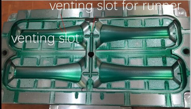
The venting grooves might be situated both at the end of the melt stream and on the P/L of the mold.
The last mentioned place is a shallow slot that is depth of 0.03-0.2mm and width of 2-6.5mm cut on the cavity side of the plastic mold.
Throughout the shot, the vent grooves won't escape much smelted resin, since the melted resin will cool-down around this location and congeal the grooves.
The placement of the vent grooves ought not to be confronting the operator to avoid unexpected splash shot of melted resin.
The gap between the ejector pins and the ejector hole, between the ejector bar stripper plate and the core insert, may be a method to release the air.
Plastic Mold Gates:
The gate of plastic mold refers to a short flow path between the runner and the cavity, which is the entrance of the resin into cavity.
It is a channel connecting the runner and the cavity.
https://www.youtube.com/watch?v=qYo7wsbfmXg&t=295s
The cross-sectional area of the gate can be equal to the runner, but it is usually reduced. So it is the smallest part of the entire runner system.
The design of the gate is related to the size, shape, mold structure, injection conditions and properties of the plastic parts.
The role of the gate :
- It could control the flow rate:
- The early solidification of the melt in this part can prevent backward flow:
- The molten material passing through is subjected to strong shearing to increase the temperature, thereby it will lower the viscosity to increase the fluidity:
- It could facilitate the separation of products and runner system.
The design of the gate shape, size, and location depends on the plastic, the size and structure of the article.
The shape of the cross section of the gate is rectangular or circular, and the cross-sectional area should be small and the length should be short.
Gate location should generally be selected where the product is thickest without affecting the appearance.
The shape, quantity, size and location of the gate will have a great influence on the quality of the plastic parts.
So gate selection is one of the key points in plastic mold design.
- Sprue Gate
Pros:
- 1) low pressure loss;
- 2)the processing is simple.
Cons:
- 1) the stress near the gate is large, and the product stress is uneven and easy to deform .
- 2) it is necessary to manually remove the gate with extra works, also it will leave obvious gate marks on the product surface.
Application:
- 1) it is suitable for large and deep barrel shaped parts. For plain parts, it is prone to warpage due to shrinkage and stress.
- 2) for parts that are not allowed to have gate marks on the surface, the gate can be set into the inner surface of the part, that is an inverted mold.
- side gate
Pros:
- 1) simple shape and easy machining.
- 2) it is easier to remove the gate.
Cons:
- 1) the product can not be separated from the gate automatically.
- 2) the gate marks will be left on the plastic part obviously
Application:
- suitable for all kinds of parts, but not for long barrel profile parts.
- pin point gate
Pros:
- 1)gate position could set on the most surface;
- 2) the gate can be separated from the part automatically.
- 3) the gate is small and the gate marks the glue is small.
- 4) the stress near the gate location is small, and the injection molded parts are not easy to warp.
Cons:
- 1) injection pressure is large, and it is not suitable to use plastic material with poor fluidity.
- 2) generally use 3 plate mold structure, the mold structure is complex, and the cost is high.
Application:
- because several gate points can be designed, it is often used for shell parts with larger surface.
- fan gate
Pros:
- 1) when the plastic flows through the gate, melt plastic distribues more evenly in the transverse direction and reduces the inner stress .
- 2) prevent air entry into the cavity and avoid defects ,such as silver streaks and bubbles.
Cons:
- 1) the part can not be separated from the gate automatically.
- 2) the gate remaining material will leave on the plastic part and it need to be trimmed manually.
Application:
- commonly used to produce thin sheet and wide parts ,and poor fluidity material, such as PC, PMMA, etc.
- submarine gate (set on ejector pins or ribs)
Pros:
- 1) the choice of gate position is more flexible;
- 2) the gate can be separated from the plastic part automatically.
- 3) both the two plate die and the three plate die can be applied.
Cons:
- 1) the cloudy area is hard to remove.
- 2) the redundant gate relics should be cut off artificially;
- 3) the pressure loss from the gate to the cavity is large.
Application:
- it is suitable for plastic parts with external appearance with no gate marks allowed.
- horn gate (also called banana gate)
Pros:
- 1) the gate can separate from the plastic part without post-processing of the gate
- 2) the gate location is inside the plastic parts, and will not effect the appearance of the part.
Cons:
- 1) the appearance of the plastic part surface may find finger printing marks.
- 2) the machining process is complex;
- 3) the unreasonable design would easily lead to break gate and block gate channel.
Application:
- commonly used for ABS, HIPS; not used for POM, PBT and other crystalline materials, also not suitable for PC, PMMA and other rigid materials, design should prevent the arc gate from broken and block the gate.
Sliders and lifters
Any structure that hinder the mold opening or ejection is referred to as undercut. The way to handle the under cut on the mold includes:sliders, lifters,core pulling, gear rotating , and etc.
The most commonly used is the sliders and the lifters.
slider
https://youtu.be/_Ayu6tcsQ6o
The slider could be set on the static or movement mold plate, and sliders on movement plateis the most widely used.
The slider generally consists of slider?body, locking block(heel), Gibbs ,cam(angle pin), wear-resistant block, spring and so on.
lifter
The lifter generally is used to handle the under cut in the interior of the plastic part,while the slider generally treats with the external under cut of the plastic parts, but the lifters structure is simpler than the slider structure.
The lifter has the function of releasing the internal under cut in the plastic parts, and it can also play the role of ejection.
So the design of the lifter on the mold generally reduces the arrangement of the ejector pins.
The lifter is composed of inclined top body, guide bushing, lifter seat and wear resistant block.
plastic mold design process:
[caption id="attachment_1998" align="aligncenter" width="780"]
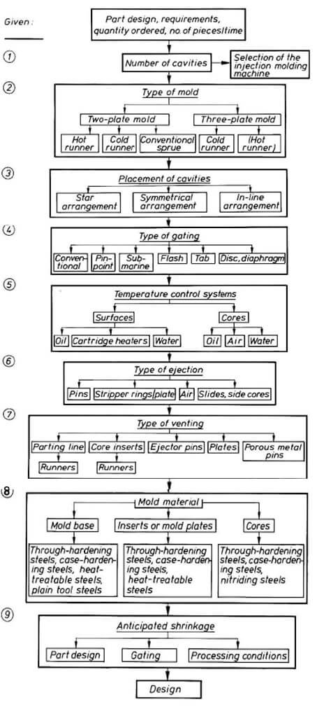 plastic mold design process[/caption]
[divider_top]
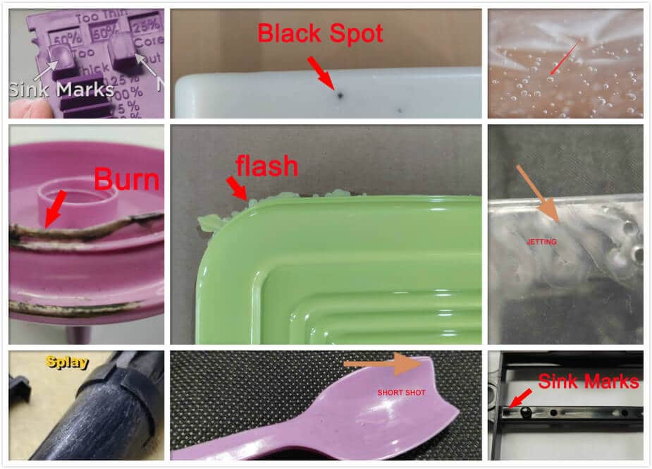
Troubleshooting of Plastic Mold Design
To sum up the discussion of the causes and cures of faults in injection moulded components, Table below should be consulted.
[one_third]Fault[/one_third]
[one_third]Generalized cause[/one_third]
[one_third_last]Possible cures[/one_third_last]
[divider_top]
[one_third]Short moulding Sinks and voids
Weld and flow marks
Poor surface finish[/one_third]
[one_third]Cavity not filling properly[/one_third]
[one_third_last]Increase injection pressure
Increase injection rate
Increase cylinder and mould temperature
Increase feed
Improve mould venting
Increase size of gate,sprue, and runner[/one_third_last]
[divider_top]
[one_third]Bum marks[/one_third]
[one_third]Lack of mould venting[/one_third]
[one_third_last]Improve mould venting[/one_third_last]
[divider_top]
[one_third]Mechanical sticking
Flash
Warping
[/one_third]
[one_third]Over-pressurization of cavity[/one_third]
[one_third_last]Reduce injection pressure[/one_third_last]
[divider_top]
[one_third]Silvering and splash marks,Decomposition[/one_third]
[one_third]Overheating of material[/one_third]
[one_third_last]Reduce cylinder temperature
Reduce effects of mechanical
heating
Increase cooling time
[/one_third_last]
[divider_top]
[one_third]Distortion[/one_third]
[one_third]Ejecting too hot[/one_third]
[one_third_last]Increase cooling time
Eject over larger area
[/one_third_last]
[divider_top]
[one_third]Jetting[/one_third]
[one_third]Linear velocity of melt too high[/one_third]
[one_third_last]Reduce velocity or break up
stream of melt
[/one_third_last]
[divider_top]
[one_third]Lamination, crazing[/one_third]
[one_third]Frozen-in stresses[/one_third]
[one_third_last]Ensure rapid filling at lowest
possible pressure
[/one_third_last]
[divider_top]


This is some really good information about plastic molding. I liked that you showed that diagram. That seems like it would help you understand molding.
ReplyDeletethanks for your information
ReplyDeleteYou must have a lot of pride in writing quality content. I’m impressed with the amount of solid information you have written in your article. I hope to read more.
ReplyDeleteI will,thanks for your information.
ReplyDeleteThanks for helping me learn more about plastic molds! My dad has been into collecting plastic models and I got curious as to how they're being made. I find it interesting that the injection system and part forming system can modify the appearance of the plastic. I should share this with my dad so he'd understand how they're made as well.
ReplyDeleteI am so glade that my website could be helpful
ReplyDelete