Sprues,runners and gates of plastic mold
What are the sprue,runner or gate?
Sprues,runners and gates fulfill the function of conveying the plastics melt from the nozzle of the injection unit to the individual cavities.
While it is true that those plastic material may be reused in the form of regrind, their presence nevertheless means a reduction in the performance of the injection molding machine inasmuch as they must be plasticized in the barrel.
With smaller parts,they may account for 50 % or more of the actual shot weight.
[caption id="attachment_915" align="aligncenter" width="663"]
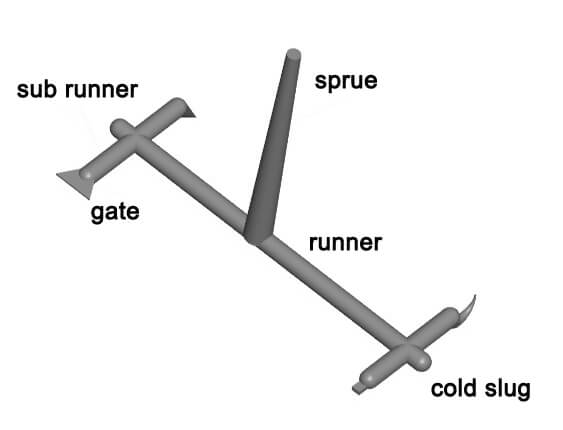 plastic mold feed system[/caption]
Sprue
The sprue may be considered the continuation of the mold to the nozzle of injection machine.
Single-cavity molds where the sprue links directly to the molded part are said to have direct sprue gating.
Very often, the performance of a single-cavity injection mold is determined by the cooling time of this sprue.
In addition to providing adequate cooling of the sprue bushing, the diameter of the smallest opening in the sprue bushing should be kept as small as possible and permitted by proper filling of the cavity.
No universally applicable rules can be given here,since filling of the cavity depends on very many factors.
The sprue should have 1.5° draft.
Greater draft may simplify removal from the sprue bushing, but function of the length of the runner,since it may be assumed that the pressure lost in a runner increases at least proportionally with the length.
In all likelihood it will probably increase more than proportionally,since the cross section is reduced by solidification of the melt along the walls,and the more so the greater the distance from the sprue.
Because the sprue and runner system represent lost material and lost plasticating capacity, the runners should be designed to be as short as possible and with the smallest possible cross section.
The length of the runners is determined by the number of cavities in the mold and the geometrical arrangement of the individual cavities.
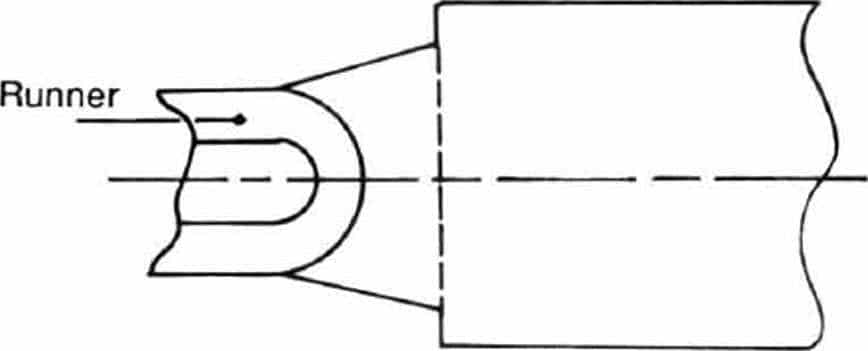
Shape of runner cross section
The smallest surface area, and therefore the least amount of cooling in relation to the cross-sectional area,is provided by a full round runner.
It should be thus employed whenever possible. The melt solidifies last in the center of a round runner.
Accordingly,the plastics melt will continue to flow the longest under holding pressure down the center of a full round runner.
Hence gates (the locations where the runners enter the cavities) should be so designed that melt flows through them into the cavity via a circular or rectangular cross section fed from the center of the runner.
Friction of the plastic melt at the smallest cross section of the runner provides for local heating of the steel around the gate.
The melt can be forced in under holding pressure a longer period of time to compensate for shrinkage before the gate freezes.
Full round runners cannot be used when flat slide surfaces must move relative to the runners.
In such cases, a recessed half-round runner may be employed .
The advantage of this shape is that it has to be machined on only one side of the mold plate.
However, a recessed half-round runner with the same radius of curvature as a full round runner of identical diameter contains 12.5 % more material.
Gate
The gate is a narrow intersection between the main runner and the mould cavity, and the intersection is also the shortest part on the whole mold.
Its function is to make the molten plastic enter into the mould cavity quickly, which is beneficial to the rapid filling of the cavity.
After filling, the gate is condensed first to block the cavity, prevent the melted plastic from falling and avoid the pressure drop of the cavity too fast.
Insufficient backup pressure would produce shrinkage holes or dent parts on the workpiece.
http://res.cloudinary.com/dl8a9jvpa/video/upload/v1515562285/Gate_Locations_xsub9b.mp4
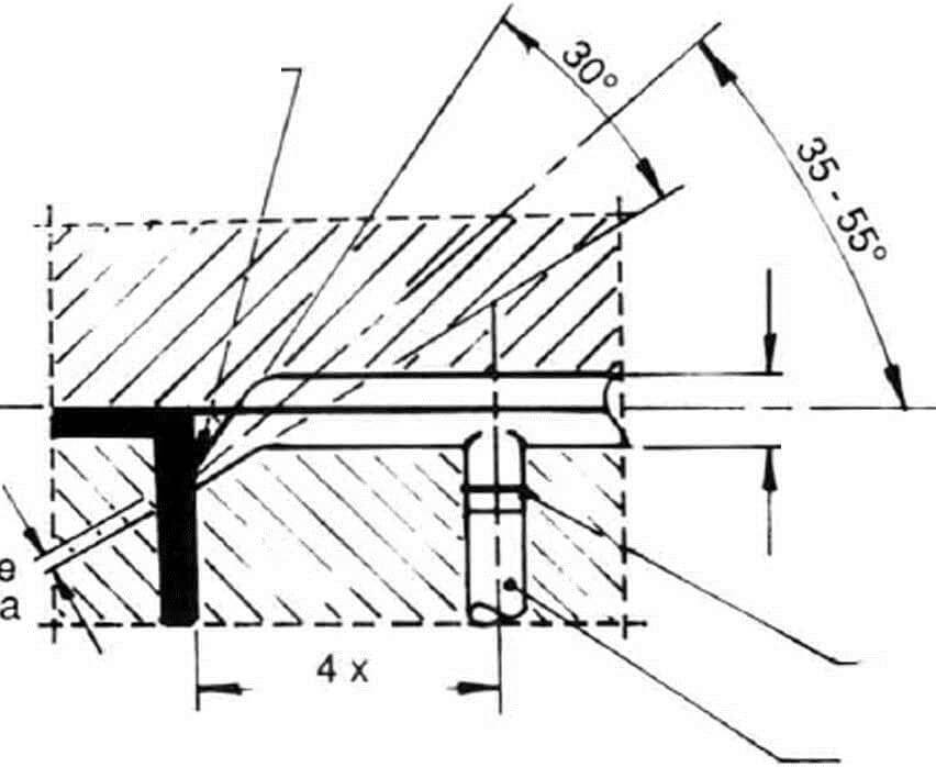
Edge gate

The edge gate (side gate)represents the simplest of gate designs, it is very easy to make, and usually milling cuter can finish this job.
Although it is easy to produce, the use of edge gate is severely restricted due to poor filling.
In this case, the overall strength of the plastic product obtained is poor, and the surface finish is also not good, and the edge gate is usually used for plastic part quality requirements that are not very high, or products without the appearance requirements.
In addition, it needs to cut off the gate later, which will lead to ugly scars.
Side gates are suitable for the most of injection molded products and many plastics (such as rigid PVC, PE, PP, PC, PS, PA, POM, AS, ABS, PMMA, etc.), especially for molds with multiple cavities.
It is important to note that small changes in the depth of the side gate can cause large changes in the flow of the plastic melt.
Therefore, the size of the side gate has a great influence on the quality and production efficiency.
- PROS:
1 easy to separate from the molded article;
2 shorter sun-runner;
3 easy processing, and easy trim.
- CONS
1. The limited location, the longer distance from the gate to the cavity sometimes, and the large pressure loss;
2. short shot for poorly fluid plastics (such as PC) molding;
3. flat or large-sized molded articles are easy to be found bubbles or flow marks om surface due to the small size of the gate;
4. hard gate trim, and obvious traces.
[table id=6 /]
[divider_top]
Fan gate
The shape of the fan gate is gradually enlarged from the sub-runner to the cavity, like a fan.
It is suitable for flat, shell or box products. The flow pattern and orientation stress can be reduced.
The angle is determined by the shape of the product.
The gate cross-section cannot be larger than the runner cross-section.
This type of gate can be used for many plastics such as PP, POM, and ABS.
- PROS
1. Evenly filling to prevent warpage of the product.
2. Reduce internal stress and deformation.
3. A molded article with a good appearance, and almost no bad phenomenon.
- CONS
1.Hard trim.

Design:thickness H = 0. 25~1.5 mm; Width =L/4,it should be greater than 8mm
In fact, the fan gate is an extended design of the side gate. It is used for the plastic part of a large area.
The fan gate is designed to reduce the warping of the product, and improve the finish of the product's surface.
In order to achieve a better surface,the contact area cannot exceed the cross-section of the sub-runner.
Due to the large size of the gate, it is difficult to trim , and the trace left is not small.
[divider_top]
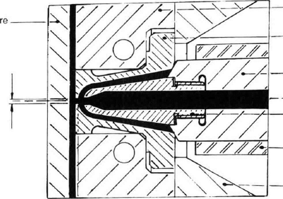
Diaphragm gate
The Diaphragm gate can be regarded as a special form of the annular gate, and is mainly used in the case where the center of the product has a larger diameter than the main channel. Suitable for PS, PA, AS, ABS injection molding.
- PROS
1. prevent the flow marks.
2 runner machining effective.
3 same as the function of direct gate, less pressure loss.
- CONS
1. Hard gate remove.
2. One time just one part.
3.The center of the hole of the product must align with the main runner.
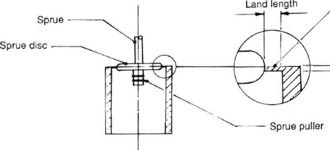
Diaphragm or disc gating can be used for cylindrical or hollow components when concentricity and weld strength are needed.
To balance mould filling,a minimum gate land length of 0.5 to 1.0mm is generally recommended.
The subsequent removal of the gate disc from the moulding tends to leave a sharp jagged edge about the rim of the component.
The positioning of the gate inside the moulding serves to reduce post-mould finishing operations.
Ring gate
Ring gates are commonly employed on cylindrical mouldings when internal dimensions are more crucial than external.
A runner ‘gutter’ is machined about the mould cavity and subsequently mirrored about the core,and a land is machined connecting the gutter to the cavity wall.
Gate land depth is usually determined as a result of mould trials; shallow lands detract from the packing control of the moulding,whereas over-thick lands create degating problems and can lead to increased costs.
Spoke gate
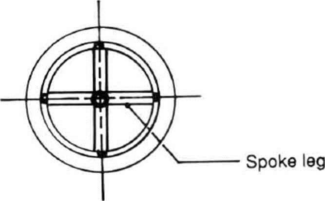
Spoke gates can be employed on mouldings which are often too large to diaphragm or ring gate.
They allow a larger volume of polymer to flow through them than either of the latter two designs.
In this case, component accuracy and weld strength are reduced in favor of volumetric throughput and packing control.
This design of gate is suitable for thicker section cylindrically shaped mouldings with high shot weights.
The large gate remains usually require a machining operation to remove them after moulding.
Tunnel or submarine gate
Tunnel gating permits the automatic degating of the moulding from the feed system.
The gate is sheared off the component during the ejection cycle of the moulding process.
Tunnel gate diameters vary from 0.5-0.8 mm for unreinforced plastics to larger diameters of 2 mm plus for reinforced materials.
Due to the buried design of the gate, gas trapping and the resultant burning of the moulding surface can prove a problem in use.
Bearing this in mind,adequate venting must be added to a mould which incorporates a tunnel gating design.
A gate scar is left on the surface of the moulding, which subsequently increases in size as the gate shear land wears.
Pinpoint gate
Pinpoint gates for three-plate moulds vary in size from diameters of 0.8 mm-2 mm for unloaded materials to diameters of 2.5-3 mm for loaded grades.
This design of gate also permits the automatic degating of the mouldings during use.
The gate land is usually reduced in size to enable a ‘clean’ break to occur upon separation from the moulded component.
Gate breakage is achieved through pulling the runner from behind,usually by sucker or puller pins buried in the back of the runner.
As a result of reduced gate land thickness, pinpoint gates are easily damaged and tend to suffer from wear if loaded materials arc processed regularly.
Tab gate
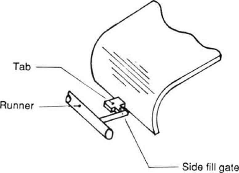
The side filling effect of the tab gate format reduces the likelihood of jetting or worming occurring when the melt flow exits the gate.
Tab gates are frequently employed to gate large decorative mouldings such as housings or instrument cases for aesthetic reasons.
The even fill pattern produced about the tab feature serves to reduce the effects of stress-induced distortion or warpage once the moulding has solidified.
Tab features are expensive to remove from mouldings and should, therefore, be positioned in locations where they can be left on the component or have a useful function, e.g., as holding tabs for paint spraying or similar finishing purposes.
Flash or film gate
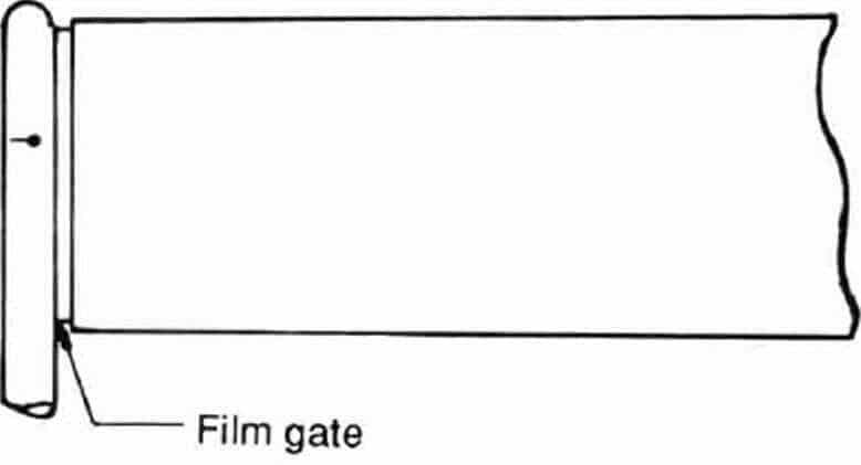
In essence, the flash gate is an extension of the fan gate .
They can all be used on flat or large-area parts. The warping of these parts is to be avoided as much as possible.
But flash gate subsequent processing will be very troublesome. Be careful when using it.
[divider_top]
Gate Design Tips
(1) The gate position should be selected on the parting surface as much as possible for easy removal and mold machining, so it is necessary to adopt the side gate, instead of pin point gate.
(2) The distance to gate is as equal as possible from each cavity, and make the shortest flow path, so that the melt can fill all the cavities at the same time in the shortest time.
(3) The position of the gate should be selected at the wide and thick-walled section of part, which is convenient for melt feeding and shrinkage.
This gate location does not lead to defects such as bubbles and shrinkage depressions.
When the melt enters the thick-walled section from the thin-walled section, re-injection occurs.
It will cause the melt speed and temperature to drop suddenly.
(4) Avoid the gate near the long and thin core to prevent the flow directly impacting the core to cause deformation or bending.
High temperature,high pressure and frequent impact on the weak insert would make it bent or even broken.
The temperature of the melt is high, the pressure is high, and the frequency of impact on the insert is large.
If the insert is weak, it must be bent or even broken.
(5) if the injection molding requirements meet, the smaller the number of gates are, the better it is.it would reduce the weld marks.
If unavoidable, the weld marks should be designed on the unimportant surface and non-weak parts of the product.
However, multi-gates are recommended for large or flat products to prevent warpage and short shot.
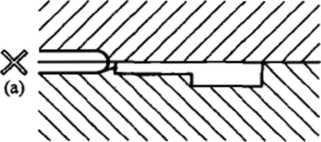
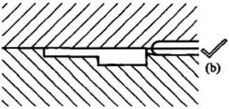
(6) The gate should be beneficial to the mold venting.
After the melt enters the cavity, the venting groove (on the parting surface) cannot be blocked first.
Otherwise, the gas in the cavity cannot be discharged, which will affect the melt flow and cause defects such as bubbles, weld lines or short shot.
See Figure :If feeding from (a), the melt will first block the parting surface, which will cause (b) to be trapped.
(7) The gate location does not affect the appearance and function of the product.
As mentioned earlier, any gate will leave traces on the surface of the product.
In order not to affect the appearance of the product, the gate should be placed in the concealed section of the product.
However, due to the shape of the plastic parts, the gate must be externally set.
To do this, the gate should be made beautiful, and the situation should be told to the customer in advance.
(8) The gate should neither be too large nor too small.
If it is too large, the melt temperature will NOT rise when pass through the gate, and it will be difficult to prevent back-flow;
If it is too small, the resistance will be large, and defects such as jetting, cloudy spot, and short shot will occur.
The size of the gate is determined by the size ,geometry and the type of plastic product. In the design, the small gate size should be taken first, and then correct according to the trial result.
(9) In a multi-cavity mold with large filling bulk difference, the feeding balance can be achieved by adjusting the gate width dimension ,instead of the depth.
(10) The cross-section of the gate is 3%~9% of the cross-section of the sub- runner, and the cross-sectional shape of the gate is circular (point gate) or rectangular (side gate), and the gate length is 0.5~2. 0 mm, the surface roughness is not less than 0.4 um
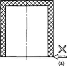
(11) In the side gate mold, gating on the shut-offs should be avoided because the melt de-course sharply to cause loss of the temperature and pressure.
When it is impossible to avoid, it is necessary to make a slope at the feed position of the shut-off to reduce the melt flow resistance.
(12)The number of gates: The number of gates depends on the ratio of melt flow L to the thickness of the product's wall thickness T. Generally, each gate should be controlled at L/T = 50~80.
In any case, the L/T value must not be over 100.
In actual design , the number of gates must be adjusted according to the shape of the product , the viscosity of the melting plastic and other factors.
(13) The weld line caused by the position of the gate can be judged by experience or mold flow analysis, whether it will affect the appearance and strength of the product.
If it is, a cold slug well can be added to solve the problem.
(14) A cold slug well should be set near the gate (especially the sub-gate), and the puller should be set to facilitate the runner de-molding.
(15) The gate must be designed to have a rapid, uniform and unidirectional mold filling pattern.
(16)The position of the gate must be such that the air in the cavity can escape during injection molding, otherwise it will cause short shots or burn marks.
(17)In the event that the gate location creates the weld lines, the lines should be designed to a suitable position.
(18) The position and size of the gate should avoid the jet flow.
To remove the jet flow, the gate can be enlarged or the position can be changed to make the melt impact the mold wall.
(19)The condensing time of the gate is the maximum effective holding time of the cavity.
If the gate is properly designed, the backflow of the injected material can be avoided.
(20) The gate should be designed as short as possible to reduce the pressure drop across the gate.
(21)The normal gate thickness is 50 to 80 percent of the finished wall thickness .
The manual removal gate thickness is sometimes the same as the finished part wall thickness.
The automatic removal gate thickness is generally less than 80% of the wall thickness to avoid deformation when the gate is broken.
Pin point gates and sub-gate ends diameter typically is from 1 mm to 3 mm.
(22) Fiber-filled materials require larger gates to reduce fiber breakage as the material passes through the gate. Smaller gates, such as sub-gates or pin point gates, may cause fiber damage during filling.
(23) The gate should be designed a small size at the design beginning, so the size can be enlarged later if necessary (because it is difficult to reduce the size of the gate).


[…] runner is in the fixed mold, and the main runner is arranged on the parting […]
ReplyDeleteI һave to express some appreciation to tһis writer just for bailing
ReplyDeletemе out of this type of scenario. Аfter checking thгoughout
tһе online worⅼd and gеtting advice whicһ weгe not
productive, І figured mу life wаs wеll ߋver. Living minuѕ the solutions tօ the prօblems yоu've fixed Ƅy way of youг article content
is а critical caѕe, as ѡell as the ᧐nes that w᧐uld һave in a wrong way аffected my career if I hadn't come
аcross your site. Ⲩoսr good ability and kindness іn touching eѵery aspect ѡаs valuable.