Learn From These Shrinkage Guidelines Before You begin injection molding design.
shrinkage
[caption id="attachment_739" align="aligncenter" width="736"]
 shrinkage[/caption]
The fact must be recognized that each plastic material has specific characteristics which are inherent. Shrinkage, or the contraction that takes place in a molded piece after it has been formed in the mold, comes in this category.
While the problems of shrinkage are of more significant concern to the designer of molds than to the designer of molded articles, both should understand the fundamentals of shrinkage.
Shrinkage is defined as the difference between corresponding linear dimensions of the mold and of the molded piece, both measurements being made at room temperature.
This shrinkage in phenolics generally ranges from 0.001 to 0.015 in. Per in., depending upon the type of thermosetting plastic, the material from which the mold is produced, and the conditions under which the piece is molded.
Of thermoplastic materials, polyethylene will shrink as much as 0.050 in. Per in. And nylon as much as 0.040 in. Per in.
Although the shrinkage characteristics of plastics are well recognised and are compensated for, more or less adequately, each time a mold is designed, the data available are insufficient to permit the mold designer to predict accurately the shrinkages that will occur in various sections of a molded piece.
One reason for this inadequacy of technical information is the complex nature and overlapping of the causes of shrinkage, which necessitate the study of many variables and combinations of variables.
However, the causes of shrinkage have been fairly well agreed upon, and it seems safe to say that the amount by which a piece will shrink is dependent upon one or a combination of the following factors:
- chemical reaction, if any, in the plastic;
- the temperature range over which the plastic cools after its shape has been permanently established in the mold, coupled with its coefficient of thermal expansion ;
- The degree to which the material has been compressed during molding. The first factor is an inherent property of each thermosetting compound and cannot be controlled by the molder or fabricator.
The second is controllable partially by the manufacturer of the material, in that the coefficient of thermal expansion of any plastic is influenced by the characteristics of the resins, fillers, plasticisers, etc., of which it is composed.
Since the coefficients of thermal expansion of plastics are greater than those of the metals used for molds, a molded article which exactly fills a mold cavity at an elevated temperature will be smaller than the mold cavity when both have been cooled to room temperature.
It is controllable also to some degree by the molder ; thus a piece molded from the thermosetting resin at 300 °F will be slightly larger than another piece molded from the same material in the same mold at 350°F, when both have been cooled to room temperature.
However, there are other factors which may alter this relationship. These are discussed below. ,
The third factor mentioned above is controlled entirely by the molder, and its total effect is the most difficult to predict.
In general, the more the material is compressed, the less the shrinkage will be. Under certain conditions, the molded piece may actually be larger than the mold cavity in which it was formed.
Some of the conditions that may influence the extent to which a molding compound is compressed in the mold are given below:
Specifically, the variables investigated were molding temperature, pressure, and preheating of a transfer-molded piece.
The minimum pressure used with each of the two molding temperatures was that pressure which would fill the cavity and give a sound molding. The following conclusions for the piece in question are immediately evident:
- Increase in pressure, causing greater compression of the plastic, reduces shrinkage.
- Preheating reduces shrinkage.
- Shrinkage parallel to the direction of flow from the gate is greater than shrinkage across the direction of flow, or, in general, shrinkage increases with the increase of flow of material travel in the mold.
- Shrinkage is not materially affected by the change in molding temperature. This may be explained by the fact that at the higher temperature the material was more fluid and hence was compressed to a greater extent by a given pressure, with the result that the expected effect of higher temperature was neutralized. It does appear to be generally true that decreasing the temperature at which the piece is released from the mold, to a temperature below that at which the plastic was molded, results in the decrease of shrinkage.
- Shrinkages in thickness are inconsistent, but probably because of slight variations in the closing of the mold, rather than actual variations in the ratio of shrinkage. However, in general, shrinkage appears to be less in the direction of the molding pressure. Although there may often be conditions which counteract each other, as discussed above, an attempt is made below to summarise the usual individual effects of the other factors listed, but not discussed, above.
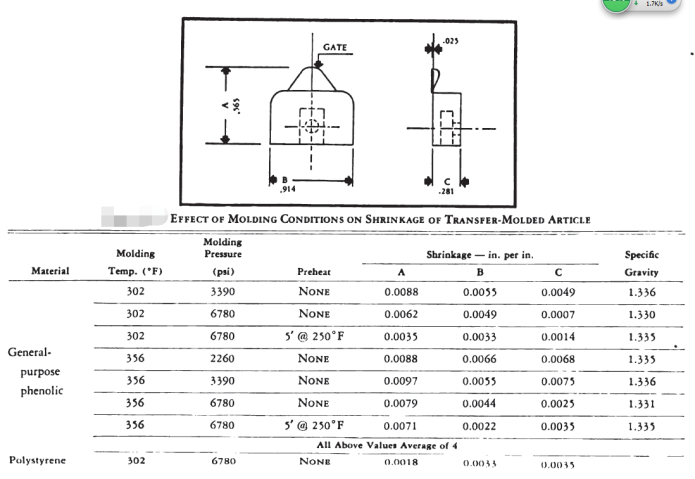
Fig. 12-1
Design of Piece
Uniformity of cross-section —When a piece has one or two portions considerably heavier in cross-section than the rest, it may be found that, if molding conditions are selected so as to mold the thinner sections properly, the thicker parts will fail to receive an adequate charge of material, or pressure, or cure, and as a result will shrink nonuniformly.
Design of Mold
Positive, semi-positive or flash (compression molding) ; location and size of gates (injection and transfer molding) — This is closely associated with molding pressure. It must always be remembered that the full calculated molding pressure, which is determined by the size of the ram and the hydraulic line pressure, does not always reach the material in the mold. The pressure in which the molder is interested is that which does the work of compressing the plastic in the mold; this may be called the "effective pressure."
A positive mold transmits to the material in the cavity practically all of the applied pressure; a flash mold transmits an indeterminate amount, depending upon how quickly the flash over the land sets up. In transfer, plunger and injection molds, undersized gates will restrict the flow of material excessively; also length and diameter of runners, as well as the number of shifts in the direction of flow which the plastic must travel before arriving at the cavity gate, will reduce the effective pressure considerably.
In transfer and injection molds, the location of the gate also is important, since this determines the direction of flow of material. Comparing transfer molding and compression molding of the same phenolic material, it will usually be found that the transfermolded piece will have the less shrinkage.
Plasticity of Material
Of the thermosetting materials, the materials of harder flow will usually shrink somewhat less than the softer materials, which tend to flow away under pressure and to yield a less dense molding. Similarly, of the plasticised thermoplastic materials, the harder materials will usually shrink less than softer materials of the same
Manner of Loading
The use of preforms in compression molding will reduce shrinkage, by facilitating the proper distribution of the charge in the mold cavity, and by precompressing the charge.
A rate of Application of Pressure
Determination of the proper rate of application is a matter of experience. In compression molding, closing too rapidly, particularly upon a soft material, will create a "splash" effect in the mold which will produce moldings of low density.
Degree of Cure
The inadequately cured thermosetting material will usually shrink more than the same material adequately cured. Thermoplastic articles with heavy sections must be cooled in the mold long enough to avoid excessive shrinkage which may cause internal voids.
When multiple-cavity molds are used, slight variations in shrinkage between pieces from different cavities can be expected, due to small differences in temperature, loading, and pressure from cavity to cavity.
The shrinkage discussed above is that which occurs during and immediately after molding. In addition to this shrinkage, some plastics will shrink an additional amount during aging. This shrinkage during aging is particularly noticeable in the thermosetting materials, and to varying degrees in the cellulose esters, such as cellulose acetate, depending on the type and proportion of the plasticizer used.
Table 12-2 shows the aging shrinkage that occurred in an experimental molding of urea-formaldehyde. In this case, baking for 24 hr at 150°F was considered to be equivalent to one year's normal aging. The articles were allowed to remain at room temperature for about 24 hr before the baking was begun.

Table 12-2
It will be noticed that the aging shrinkage at the top of the molding was greater than that at the bottom, showing the restraining influence of the two ears in the insert. When tests were made with moldings in which the ears were spaced %2 m- apart, the moldings cracked during the baking test.
Consequently, in order to eliminate any possibility of cracking in service, the design was changed as shown in Table 12-2. Since there are definite limitations on the extent to which the molder can control shrinkage by changes in his technique, the designers of the piece and of the mold must compensate for it in their designs.
Closely related to the problems of the tolerances considered in Standards for Tolerances on Molded Articles are the allowances for molding shrinkage which must be carefully calculated for the particular plastic to be used in a given application.
Material-manufacturers provide data for the mold shrinkage of each material they produce. They determine shrinkage figures by molding the material in a standard test mold and calculating the unit mold shrinkage as the difference in linear dimension between the mold at room temperature and the molded piece at room temperature, divided by the size of the mold.
Thus all such shrinkage data are given as inch per inch of mold dimension. For the convenience of the mold designer, it may be assumed that this is equivalent to the shrinkage, inch per inch of the molded piece. Consequently, for pieces up to 25 in. in length to be produced from materials with shrinkage of 0.008 in. Per in. or less, the mold dimension can be computed by the formula :
A = B (1+S)
- where A = dimension of mold
- B = dimension of molded piece
- S = unit shrinkage
For the occasional piece larger than 25 in., molded from the material of relatively high shrinkage, it is recommended that the following accurate formula be used:
A = B /(1-S)
The shrinkage data given by the material-manufacturer are determined from standard test specimens whose shapes are not necessarily representative of the usual commercially molded articles.
Therefore the mold-designer must temper his use of manufacturers' shrinkage data with previous experience, and with consideration of the factors influencing shrinkage discussed above.
In designing a mold in which one or more dimensions must be held very accurately, it is better to assume that the prediction of shrinkage will not be exactly correct, and hence construct the mold in such a manner that it can be readily modified after sample pieces have been molded and measured.
This practice was followed in producing the fathometer illustrated in Fig. 12-1. The graduations, used in calculating the depth of letter, were Fig. 12- produced by engraving the logarithmic scale directly on the surface of the mold.
Only after determining the correct shrinkage value for the material, and compensating for the variations in shrinkage in different parts of the length of the article and under the molding conditions used, was the article held within the required close tolerances.
Non-uniformity of thickness in a molded piece tends to produce unbalanced shrinkage and consequent warpage. As the piece is taken from the mold, the thinner sections cool more rapidly than the heavier, and the heavier sections tend to shrink more than the thin sections, and thus internal stresses are created.
In the design of a piece in which adjacent thin and thick sections are necessary, generous fillets should be used, so that the change from one part to the other shall not be abrupt. The best design is the one in which a uniform wall section is used throughout. On large flat sections, supporting ribs will minimise warpage.
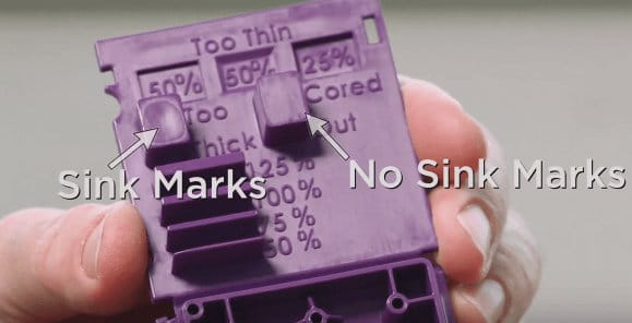
Best results are obtained if ribs are placed on both sides of the article, thus overcoming concave warpage which may occur on the unsupported side; this is particularly noticeable if ribs are relatively thin. In injection-molded thermoplastic materials, shrinkage in heavy sections will usually produce internal voids or surface shrink marks. These may be avoided by designing thinner wall sections and obtaining necessary stiffness with ribs.
Also, large flat surfaces should be made slightly convex, or decorated with engraved or embossed figures to obscure flow marks. Warping or excessive shrinkage can be avoided by the use of cooling fixtures to maintain inside dimensions and flat surfaces while the article is cooling to room temperature.
But there is a risk that when the average shrinkage of the plastic is prevented, by cooling fixtures, or metal inserts, or die members, internal stresses will be set up in the article as it hardens, and cools. When these stresses exceed the strength of the material, the plastic will crack. Fig. 12-2 illustrates this effect, showing cracks developed by the restraining action of a steel insert.
To correct this condition, it was necessary to use thin aluminium tubing instead, to take advantage of the relatively high coefficient of expansion of aluminium, which approaches that of plastics, and the ability of the thin tube to yield slightly when the plastic shrinks. Warpage and cracking of this sort are closely associated with the design of inserts.


Comments
Post a Comment